
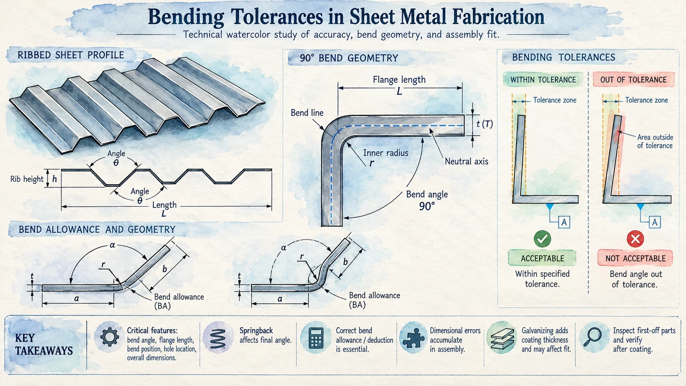
Bending tolerances help sheet-metal parts match their drawings and fit together as intended. Small variations in angles, flange lengths, bend positions and hole locations can accumulate across an assembly.
Accurate bending is essential in the manufacture of metal cabinets, racks, enclosures, brackets and structural components. It helps maintain consistent product quality and makes assembly more predictable.
A small deviation in a bend angle, flange length or bend position can change a component’s overall dimensions. When several parts are assembled, these variations can add up and cause alignment problems, gaps, interference or installation difficulties. Dimensional accuracy should therefore be considered during design, fabrication, inspection and final assembly.
What are bending tolerances?
A bending tolerance is the permitted variation between the dimension or angle specified on an engineering drawing and the result achieved during manufacturing.
For example, if a drawing specifies a 90° bend, the acceptable variation depends on the tolerance stated on the drawing or in the applicable manufacturing standard. Flange dimensions must also remain within their specified limits.
Bending tolerances commonly apply to:
- Bend angle: The permitted variation from the specified angle.
- Flange length: The acceptable variation in the formed flange length.
- Bend position: The permitted variation in the bend’s location.
- Hole position: The accuracy of holes relative to bends, edges and other features.
- Overall dimensions: The finished component’s length, width and height.
- Flatness and squareness: The component’s ability to maintain the required geometry.
These tolerances help parts remain interchangeable and assemble without unnecessary adjustment.
Factors that affect bending accuracy
Material thickness and properties
Material thickness, hardness and other mechanical properties affect the bending force and final bend angle. Variations in thickness can change finished dimensions, even when the same machine settings are used.
Springback
Springback occurs when material partially returns toward its original shape after the bending force is removed. Its amount depends on the material properties, thickness, bend radius and bending method. Manufacturers compensate for springback to achieve the required final angle.
Bend radius and tooling
The punch and die used in a press brake influence the bend radius and final geometry. Incorrect tooling can produce inconsistent bends, surface damage or dimensional deviations.
Machine setup and operator control
Incorrect machine settings, inaccurate back-gauge positioning, worn tooling and inconsistent operating methods can create variation between components. Suitable setup procedures and regular inspections help maintain repeatable results.
Bend allowance and bend deduction
During bending, material stretches and compresses around the bend area. The flat pattern therefore cannot always be calculated by simply adding the finished flange dimensions. Correct bend allowance or bend deduction calculations are needed to achieve the required finished dimensions.
How bending tolerances affect assembly
Hole alignment and fastener installation
If a hole is positioned too close to or too far from a bend, its final location may differ from the intended position. Bolt holes can then become misaligned during assembly, requiring workers to reposition parts or make adjustments. These steps increase assembly time.
Unapproved drilling or enlarging of holes can affect product quality. It should not be used as a substitute for meeting the drawing requirements.
Frame squareness
In a rectangular frame or metal rack, variations in bend angles and flange lengths can leave the assembled structure out of square. This can create uneven corners, twisted frames and difficulty installing shelves, doors, covers or other components.
Gaps and interference
Incorrect flange dimensions can create unwanted gaps between connected components. A flange that is too long may interfere with an adjacent part. Either condition can affect the finished product’s appearance, stability and function.
Accumulation of dimensional errors
Dimensional errors can accumulate when several components are assembled. If multiple parts have small deviations in the same direction, the total variation across the assembly can become significant. Individual components may appear acceptable while their combined dimensions cause the assembly to exceed its overall tolerance.
For this reason, control critical dimensions at both the component and assembly levels.
Applying the checks to an electrical enclosure
During fabrication and assembly, check these features against the approved engineering drawing:
- Overall width, height and depth.
- Bend angles and flange dimensions of individual parts.
- Position and alignment of mounting holes.
- Squareness of the assembled frame.
- Clearance between adjacent components.
- Fit of shelves, covers, brackets and other mating parts, where applicable.
If a fabricated side panel has an incorrect bend angle, its flange may not align with the adjoining frame member. This can affect hole alignment and distort the assembly during fastening. Incorrect flange lengths can also change the structure’s effective overall dimensions. Checking critical dimensions before assembly helps identify these issues early.
Important: Overall dimensions alone do not establish the allowable bending tolerances. Take the acceptance limits from the approved drawing, its general tolerance notes or the applicable manufacturing specification.
A drawing-based specification checklist
Before manufacturing begins, identify the following information on the engineering drawing.
| Drawing feature | What to check | Effect on assembly |
|---|---|---|
| Overall dimensions | Width, height and depth. | Ensures the product fits within its required envelope. |
| Bend angles | Specified angle and permitted variation. | Controls squareness and component fit. |
| Flange dimensions | Lengths and formed profiles. | Prevents gaps and interference. |
| Hole locations | Dimensions from specified datums or edges. | Ensures fasteners align correctly. |
| Bend radius | Specified or approved radius. | Helps maintain geometry and material integrity. |
| Material thickness | Specified material gauge or thickness. | Influences bending and fit. |
| Assembly dimensions | Critical distances between mating features. | Confirms overall fit and interchangeability. |
| Surface finish | Required finish and coating condition. | Supports corrosion protection and appearance. |
This is a drawing-review checklist, not a transcription of drawing notes. Confirm exact numerical tolerances from the original drawings.
How hot-dip galvanizing affects fabricated parts
Hot-dip galvanizing protects steel from corrosion by immersing prepared components in molten zinc. It is commonly used for fabricated metal products exposed to demanding environments. Galvanizing should also be considered when planning fabrication and assembly.
Coating thickness and dimensional clearance
The zinc coating adds material to the component’s surface. This can affect close-fitting interfaces, threaded features, holes and narrow clearances. Review critical dimensions and clearances before galvanizing, and account for the specified coating where components fit closely together.
Distortion during galvanizing
The heating and cooling associated with galvanizing can cause dimensional changes or distortion, particularly in fabrications with uneven thicknesses, asymmetrical designs or significant residual stresses. Correct fabrication practices, suitable component design and appropriate galvanizing procedures can reduce these risks.
Venting and drainage
Hollow sections and enclosed areas need suitable vent and drain openings where the galvanizing process requires them. Coordinate their locations with the engineering design to support safe processing and proper coating coverage.
Post-galvanizing inspection
After galvanizing, check coating quality, critical dimensions and any defects that could affect assembly. Repairs or modifications should follow the approved procedure and applicable coating requirements.
For an assembly, plan bending, trial fitting, galvanizing and final assembly as a sequence. This helps the team consider coating requirements and critical dimensional clearances together.
Best practices for controlling bending tolerances
- Review drawings before production. Identify critical dimensions, bend angles, material thicknesses, hole positions and tolerance notes.
- Use accurate flat-pattern calculations. Apply suitable bend allowance or bend deduction values for the material and tooling.
- Verify machine settings. Confirm the punch, die, back gauge and bending parameters before producing the full batch.
- Inspect the first-off component. Measure the initial part and confirm that it meets drawing requirements before continuing production.
- Use suitable measuring instruments. Calipers, angle gauges, height gauges and dedicated fixtures can help verify critical features.
- Maintain consistent manufacturing methods. Standardized setup procedures and operator training help reduce part-to-part variation.
- Conduct a trial assembly when needed. Confirm that mating components fit correctly before applying the final protective coating.
- Inspect after galvanizing. Check relevant dimensions and coating condition, especially at close-fitting interfaces.
- Record inspection results. Document measurements and nonconformities so recurring manufacturing issues can be identified and corrected.
Benefits of maintaining the specified tolerances
Maintaining specified tolerances can:
- Reduce assembly time and manual adjustment.
- Improve dimensional consistency between production batches.
- Minimize material waste and rework.
- Improve hole alignment and fastener installation.
- Help maintain the structural geometry of the finished product.
- Support effective corrosion-protection planning.
- Improve product quality and customer satisfaction.
These benefits matter especially in batch production, where parts need to fit together consistently without repeated modification.
Conclusion
Bending tolerances are essential to sheet metal fabrication because they determine the dimensional accuracy and fit of manufactured components. Variations in bend angles, flange lengths, hole positions and overall dimensions can create assembly problems even when each component appears visually acceptable.
Controlling critical dimensions from fabrication through final inspection helps an assembly align correctly, remain square and accept its mating components. Hot-dip galvanizing also needs to be considered because the coating adds thickness and the process can affect some fabricated dimensions.
By reviewing engineering drawings, applying correct bending calculations, inspecting the first-off component, controlling manufacturing processes and checking critical features after galvanizing, manufacturers can reduce rework and build more reliable assemblies. Accurate bending supports efficient assembly, consistent product quality and dependable finished products.