
1. What is DOL starting?
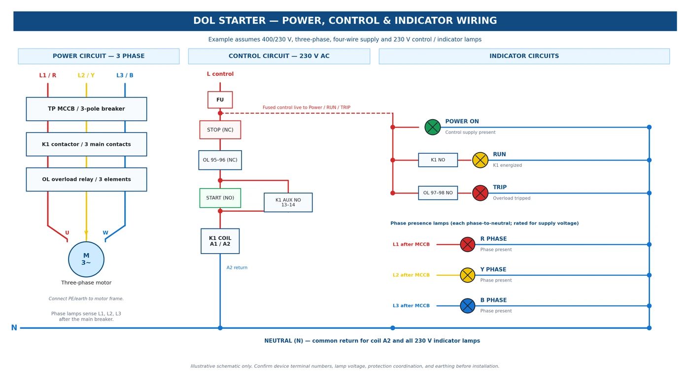
Direct-On-Line (DOL) starting connects a three-phase induction motor directly to its rated supply voltage through a contactor and protective devices. It is simple and economical, but the high starting current must be acceptable to the supply network and the driven equipment.
2. Main components and indicator functions
- MCB / short-circuit device: provides short-circuit protection when correctly selected and coordinated.
- Contactor (K1): connects and disconnects the motor supply.
- Overload relay (OL): opens its normally closed control contact during an overload; it does not replace short-circuit protection.
- START (NO) and STOP (NC): start the coil and stop it by opening the control circuit.
- Power ON lamp: indicates the monitored control supply is present.
- RUN lamp: normally lights through a K1 auxiliary NO contact; it confirms the contactor is energized, not necessarily that the shaft is turning.
- TRIP lamp: can be wired through the overload relay NO auxiliary contact (often terminals 97–98).
- R/Y/B phase lamps: each should monitor its corresponding phase to neutral on a 400/230 V system; they indicate phase presence only at their sensing points.
3. Calculate the motor current
Example motor: 5.5 kW output, 400 V three-phase, efficiency η = 0.90 and power factor PF = 0.85.
I_FL = (P_out × 1000) / (√3 × V_LL × η × PF)
I_FL = 5500 / (1.732 × 400 × 0.90 × 0.85) ≈ 10.4 A
This is an estimate. Use the actual motor nameplate current for final selection and overload settings.
4. Estimate the starting current
If the manufacturer specifies a starting-current multiple of 6, the estimate is:
I_start ≈ 6 × I_FL = 6 × 10.4 ≈ 62.4 A
The actual starting current and its duration vary by motor and load. Check the motor data or manufacturer documentation.
5. How to select the components
Use the current calculation as a starting point, then check the motor nameplate, starter manufacturer tables, supply conditions and local electrical standards. The selections below are examples, not a complete installation design.
Step 1 - Select the contactor
Choose a three-pole contactor with an AC-3 rating appropriate for a squirrel-cage induction motor, and verify both its rated motor power at 400 V and its operational current. Also match the contactor coil voltage to the actual control supply.
| Component | Published data | Selection note |
|---|---|---|
| Example: Schneider Electric LC1D12P7 | Published rating: 12 A AC-3; 5.5 kW at 380–400 V, three-phase, with a 230 V AC coil. | It is a candidate for a 5.5 kW, 400 V motor, subject to the manufacturer's application data, duty and conditions. |
| Example: Schneider Electric LRD16 | Published adjustment range: 9–13 A, Class 10A. | The range includes the estimated 10.4 A. If the motor nameplate current is 10.4 A and the manufacturer's instructions allow it, set the relay to approximately 10.4 A. Otherwise use the actual nameplate value and applicable requirements. |
Step 2 - Select the overload relay
Choose an adjustable overload relay whose setting range includes the actual motor nameplate current. Do not choose a range based only on the calculated estimate if the nameplate differs.
Step 3 - Select the MCB / short-circuit protection
Do not size the MCB from full-load current alone or simply apply a fixed multiplier. The device must ride through the motor's starting current for the full starting duration, protect the cable, and provide adequate short-circuit breaking capacity.
Starting-current check: with the example estimate of 62.4 A, check the selected tripping curve against the motor's actual start-current/time profile.
Cable and fault check: confirm cable current-carrying capacity, voltage drop, prospective short-circuit current, breaking capacity and required disconnection time.
Coordination check: use the starter/contactor manufacturer's published coordination tables for the selected breaker or fuses and overload relay.
Candidate only: a 16 A C-curve MCB may be investigated for this example, but cannot be approved from the current calculation alone. Its suitability must be checked against starting duration, cable protection, fault level and coordination data.
Component selection summary
| Component | Example result | How to verify |
|---|---|---|
| Motor current | ≈ 10.4 A calculated | Use motor nameplate current for final selection. |
| Starting current | ≈ 62.4 A estimated (6×) | Confirm motor starting-current data and duration. |
| Contactor | LC1D12P7: 12 A AC-3; 5.5 kW at 400 V; 230 V AC coil | Match motor rating, coil voltage, duty and application tables. |
| Overload relay | LRD16 example: 9–13 A | Set to the appropriate nameplate value per instructions. |
| MCB / short-circuit device | No final rating specified | Verify starting curve, cable protection, fault level and coordination. |