
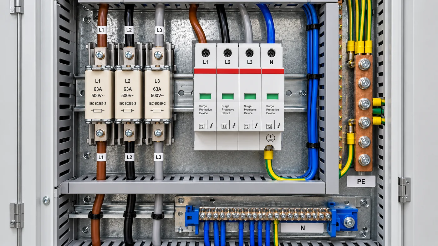
A detailed guide to SPD types, electrical ratings, 3+1 and 4+0 configurations, backup protection, installation and maintenance.
Technical note: SPD selection and installation depend on the actual earthing arrangement, manufacturer instructions and applicable local rules. The examples in this guide are not universal sizing instructions; design and work should be checked by a qualified electrical professional.
Why surge protection matters in modern panels
Modern electrical installations depend heavily on electronic equipment such as programmable logic controllers (PLCs), variable frequency drives (VFDs), digital energy meters, automatic transfer switch (ATS) controllers, computers, communication devices and industrial automation systems. Although these devices improve operational efficiency and system performance, many are sensitive to sudden changes in electrical voltage.
One of the major threats is transient overvoltage, commonly called a voltage surge. It may originate from lightning activity, switching operations, electrical faults or disturbances in the distribution network. Even a short surge can damage electronic components, reduce equipment life, interrupt production and cause expensive downtime.
Surge Protection Devices (SPDs) are therefore valuable components of Main Distribution Boards (MDBs), Sub-Main Distribution Boards (SMDBs), Distribution Boards (DBs), ATS panels and industrial control panels. Correct selection involves much more than choosing a high kA rating: system voltage, earthing, lightning exposure, discharge capability, voltage protection level and protective-device coordination all matter.
What is a Surge Protection Device?
An SPD is a protective device designed to limit transient overvoltages and divert surge currents away from sensitive electrical equipment. In normal service, a parallel-connected SPD presents high impedance and does not carry the normal load current. When a high transient voltage occurs, its nonlinear components conduct and limit the voltage across the protected installation. After the surge subsides, a healthy SPD returns to its high-impedance state.
Most power-system SPDs contain metal-oxide varistors (MOVs), spark gaps or combinations of protection technologies. SPDs must not be confused with circuit breakers: MCBs and MCCBs primarily address overcurrent and short-circuit faults, whereas SPDs address short-duration surge voltages.
What causes voltage surges?
Lightning strikes
A direct lightning strike to a structure or an overhead line can introduce high-energy surge currents. Nearby strikes can also induce overvoltages in power and communication cables through electromagnetic coupling. A surge travelling from an overhead supply may reach the main distribution board and expose downstream equipment to damaging voltages.
Switching operations
Switching inductive motors, transformers, capacitor banks, contactors and circuit breakers can create voltage transients. These may be conducted along distribution circuits and disturb electronic equipment, especially where long cables and sensitive controls are present.
Faults and abnormal supply conditions
Some faults and supply disturbances produce transient overvoltages. However, sustained overvoltage, undervoltage and missing-phase conditions require other forms of monitoring or disconnection. A normal SPD is not a voltage regulator or a substitute for an over/under-voltage protection relay.
Why are SPDs important in panel boards?
Modern LV panels often combine traditional switching equipment with delicate digital meters, relays, controllers and communication hardware. Suitable surge protection reduces the probability of surge-related equipment damage and helps maintain service continuity.
- Protects sensitive control electronics, meters, VFDs, PLCs and communication systems from specified surge events.
- Can reduce surge-related repair costs and unplanned operational downtime.
- Supports insulation coordination and an overall approach to electrical protection.
- Can protect distributed equipment through coordinated SPDs at several distribution levels.
No SPD can guarantee protection against every lightning or overvoltage event. Performance depends on the SPD, the available surge energy, installation geometry, earthing and bonding quality, and coordination across the system.
Types of surge protection devices
Type 1 - lightning current protection
Type 1 SPDs are tested with a 10/350 microsecond lightning-current waveform and are designed to conduct high-energy partial lightning currents. Their defining test rating is Iimp (impulse discharge current). They are typically selected at the electrical installation origin where the design requires lightning-current discharge capability - for example, buildings with an external lightning protection system (LPS).
For specified IEC-based arrangements, 12.5 kA per relevant protection path is a familiar Type 1 design value, while larger ratings may be necessary. The correct rating must follow the lightning risk, system topology and lightning protection coordination; it cannot be selected from a single generic figure.
Type 2 - distribution board protection
Type 2 SPDs handle specified induced-lightning and switching-related impulses and are tested using an 8/20 microsecond current waveform. Their important characteristics include nominal discharge current In and maximum discharge current Imax. Modular Type 2 SPDs are widely used in MDBs, SMDBs and industrial distribution panels, either as main protection where appropriate or as coordinated downstream protection.
Type 3 - equipment-level protection
Type 3 SPDs provide additional protection close to sensitive equipment. They are commonly associated with combination-wave tests and lower surge energy duty than Type 1 and Type 2 devices. They should form part of a coordinated protection design rather than serving as the only main incoming surge protection in an exposed installation.
Understanding important SPD ratings
Nominal voltage (Un) and maximum continuous operating voltage (Uc)
Un is the nominal electrical system voltage. In a common 400/230 V, 50 Hz network, voltage is approximately 400 V phase-to-phase and 230 V phase-to-neutral. Uc is the maximum RMS voltage that may be continuously applied to a given SPD mode. For example, a 275 V AC Uc phase-to-neutral element may be suitable for some 230 V systems, subject to earthing and manufacturer requirements. The Uc must tolerate normal system variation and relevant temporary overvoltage conditions.
Voltage protection level (Up)
Up is the SPD manufacturer’s declared voltage-limiting performance under defined tests, often expressed in kV. A value such as Up ≤ 1.5 kV does not indicate the operating supply voltage; it describes a surge test characteristic. Shorter connecting conductors and a suitable installation layout are essential because conductor inductance may increase the real voltage reaching equipment above the declared Up.
Nominal discharge current (In)
In is the peak 8/20 µs current used in specified duty testing for Type 2 protection. For example, In = 20 kA (8/20 µs) is a surge test characteristic, not a continuous 20,000 A current rating.
Maximum discharge current (Imax)
Imax is the declared maximum 8/20 µs surge current for Type 2 SPDs. Typical catalogue values include 20 kA, 40 kA and 65 kA, depending on device and protection mode. A larger Imax does not automatically make a device preferable: In, Up, Uc, available fault current and protective coordination also matter.
Impulse current (Iimp)
Iimp applies to Type 1 lightning-current withstand, typically using a 10/350 µs waveform. For example, Iimp = 12.5 kA (10/350 µs). The 10/350 µs and 8/20 µs waveforms represent different current-duration and charge characteristics; their kA ratings cannot be directly compared.
Short-circuit current rating (Isccr)
Isccr describes short-circuit suitability under the specified conditions, including the manufacturer’s required backup protective arrangement. A 40 kA Imax SPD is not therefore a 40 kA fault-interrupting circuit breaker. The entire protective assembly must be suitable for the prospective power-frequency short-circuit current at the installation point.
Temporary overvoltage (TOV) performance
Temporary overvoltages can arise from abnormal neutral conditions, earth faults and network disturbances. SPD TOV behaviour must match the installation. A normal SPD is not intended to monitor or regulate long-lasting supply abnormalities.
Understanding 3+1 and 4+0 configurations
What is a 3+1 SPD?
A 3+1 SPD uses three protection paths between the phase conductors and neutral, together with a fourth protection path between neutral and protective earth. A common arrangement uses three metal oxide varistors (MOVs) between the phases and neutral and a spark-gap device between neutral and PE.
Protection paths:
- L1 to N
- L2 to N
- L3 to N
- N to PE
This configuration is commonly used in TT installations and may also be used in TN-S installations. It provides differential-mode protection between phase and neutral and a coordinated path for common-mode surge currents through the N - PE element.
What is a 4+0 SPD?
A 4+0 SPD uses separate protection paths from the three phase conductors and the neutral conductor to protective earth. Its protection paths are:
L1 to PE
L2 to PE
L3 to PE
N to PE
This configuration is used in appropriate system arrangements, including certain TN-S applications.
Which configuration is correct?
The correct choice depends on the earthing system, RCD arrangement, applicable installation rules, and the manufacturer's approved connection scheme. For TT systems, the 3+1 arrangement is commonly selected because of the neutral-to-earth protection requirements and its suitability within the specified protection architecture For TN-S systems, both 3+1 and 4+0 arrangements may be applicable. For TN-C systems, where a combined PEN conductor is used, a 3+0 configuration is commonly applied. Important: A product labelled “3P+N” does not automatically identify whether its internal connection scheme is 3+1 or 4+0. Always verify the manufacturer's wiring diagram.
Why does an SPD need backup MCB or fuse protection?
An SPD can fail under extraordinary surge energy, abnormal supply conditions or at the end of its service life. A fault may then develop inside the unit. Manufacturer-approved short-circuit protection is needed to limit and safely clear power-frequency fault current.
Depending on the SPD design, protection may include an internal thermal disconnector, integrated short-circuit protection, a specified upstream device or a dedicated external MCB or fuse. The correct combination must safely interrupt the prospective fault current and withstand expected surge impulses without unnecessary disconnection. Two SPDs with the same Imax can require different backup protection.
Check the manufacturer’s recommended fuse/MCB type and maximum or mandatory rating, SPD Isccr, device interrupting capacity, cable protection, prospective fault current and any system selectivity requirements.
Correct SPD installation inside a panel
Place the SPD near the relevant incoming conductors
SPDs are normally placed near the incoming supply and main bonding/earth terminals, with additional downstream protection where necessary. The exact relation to RCDs, main breakers, changeover sources and neutral-earth bonding points depends on the electrical system design.
Keep leads short and direct
Fast impulse currents produce inductive voltage drops along conductors. Consequently, long SPD connections can increase the voltage reaching equipment. IEC-based installation guidance commonly targets approximately 0.5 m or less for the combined effective connection path between the line connection, SPD and earth terminal, where practicable. Avoid unnecessary loops and bends.
Select adequate connecting conductors
Conductors must satisfy the product terminals, short-circuit withstand, surge duty and the applicable wiring standard. IEC-based guidance commonly refers to at least 6 mm² copper for a Type 2 SPD connection to the main PE arrangement and 16 mm² copper for Type 1 at the origin, under specified conditions. Live-side conductors, local exceptions and any larger requirements must be checked separately against the product instructions and applicable rules. These numbers are not universal sizing instructions.
Earthing and bonding
Surge protection only performs as intended when protective earthing and bonding are correctly designed. The main earthing terminal, protective conductor bar, conductive enclosures and required equipotential bonds must all be considered. An SPD does not replace a safe earthing installation.
Coordination with RCDs
Surge paths can cause unwanted RCD operation if the arrangement is poorly coordinated. TT/TN system requirements, RCD placement, protection configuration and residual-current sensitivity must be verified so that fault protection is not defeated.
Separate wiring appropriately
Reduce loop area and unnecessary parallel runs between unprotected incoming and protected outgoing conductors. Good layout can minimize coupling of surge energy and is an important part of panel construction quality.
Coordination between Type 1, Type 2 and Type 3
Large facilities often need coordinated SPDs at several levels. A Type 1 or Type 1+2 SPD may be provided where the lightning protection design requires it at the main supply; Type 2 units may follow in distribution panels; and Type 3 devices may be placed close to sensitive electronic equipment.
Additional SPDs may be appropriate for long cable runs, often assessed when protected equipment is more than about 10 m from the upstream SPD, or where installation geometry and equipment impulse ratings justify extra protection. Coordination and separation requirements must follow manufacturer guidance; simply installing many uncoordinated SPDs does not ensure proper operation.
AC SPDs compared with DC SPDs
SPDs for AC and DC circuits are not automatically interchangeable. In photovoltaic installations, the DC side of an inverter may require products designed and tested for PV DC duty, compatible with the array’s maximum voltage and fault characteristics. IEC 61643-31 addresses SPDs for PV DC installations; the AC side of an inverter may need separately selected AC SPDs.
Inspection and maintenance
SPDs are protective devices with a finite service life. Their internal components may deteriorate due to repeated surge exposure, ageing, and abnormal electrical conditions. Many modular SPDs are equipped with visual operating-status indicators. Depending on the manufacturer, a green indicator commonly represents a serviceable condition, while a red indicator may indicate end-of-life or replacement requirements. However, color meanings must always be confirmed from the specific product documentation. SPDs should be included in periodic electrical panel inspections.
Maintenance checks should include:
- Inspecting the SPD's operating-status indicators.
- Checking the associated backup fuse or circuit breaker.
- Inspecting terminals and conductor connections.
- Checking earthing and bonding connections.
- Looking for overheating, discoloration, or physical damage.
- Checking remote monitoring signals, where installed.
- Replacing failed SPD modules or cartridges with approved replacements.
- Recording replacements and maintenance activity.
Maintenance must be performed by qualified personnel using appropriate isolation and electrical safety procedures.
Insulation resistance tests or other electrical tests must not be performed through SPDs unless the manufacturer's instructions specifically permit them. Otherwise, the testing voltage may damage the protective components or distort the results.
Conclusion
Surge Protection Devices are essential components of modern low-voltage distribution and industrial automation protection. They reduce exposure to damaging short-duration overvoltages produced by lightning and switching disturbances, helping protect electronic equipment and reduce unexpected downtime.
Effective SPD selection is not a matter of choosing the highest available kA value. The engineer must evaluate system voltage, earthing, surge duty, SPD type, Uc, Up, In, Imax or Iimp, prospective short-circuit current, protective-device coordination, physical connection length and correct bonding. In large or sensitive installations, the protection arrangement may need several coordinated stages.
The best SPD is the one correctly selected, coordinated and installed for the actual electrical installation - not necessarily the one with the highest nameplate discharge-current rating.